The main objective with this competition is to build a robot that can autonomously navigate around a course staying in-between white lines and avoiding obstacles in its path. You can visit the competition website at igvc.org.
How we did
During the competition, we failed to qualify. Our design report is in the links at the top of this page.
Software
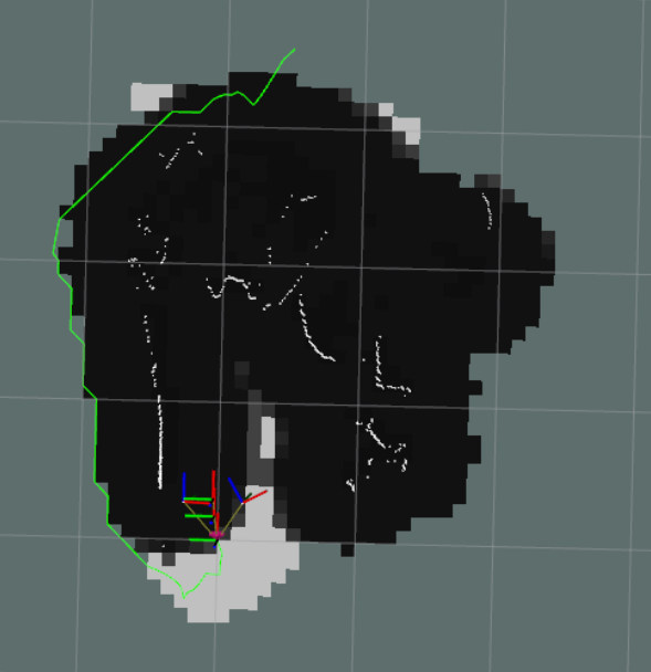
The software portion of this competition was the most difficult part of the challenge. The main problems we were faced with were obstacle detection and path planning around those obstacles. To detect obstacles we used a Hokuyo 2D scanning lidar and 2 Intel Realsense D435 depth cameras. The general algorithm used was to determine what pixels have white lines using image thresholding, then convert those pixels to 3D points in the world in front of the robot. We then add all the points the lidar hits to the obstacle list. We then use a SLAM algorithm to create a map and localize the robot in it. Next we can create a cost map around all the obstacles and build a path that navigates forwards through the cost map to avoid all the obstacles. This path is then converted to a forward velocity and turn angle which are both passed to our drive control system that controls each individual motor to drive the robot in the desired direction.
Mechanical
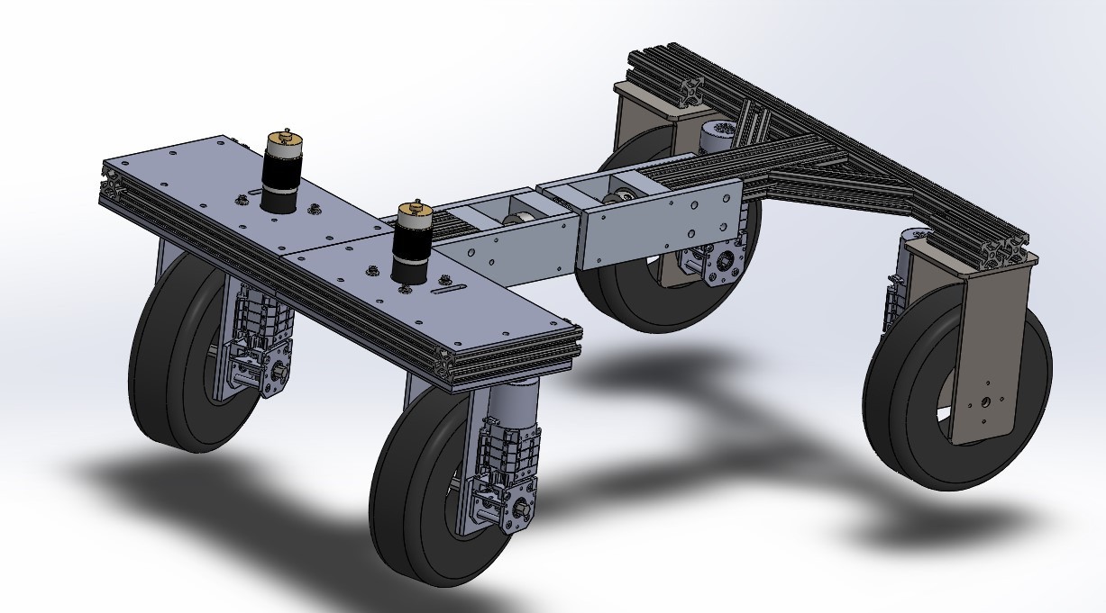
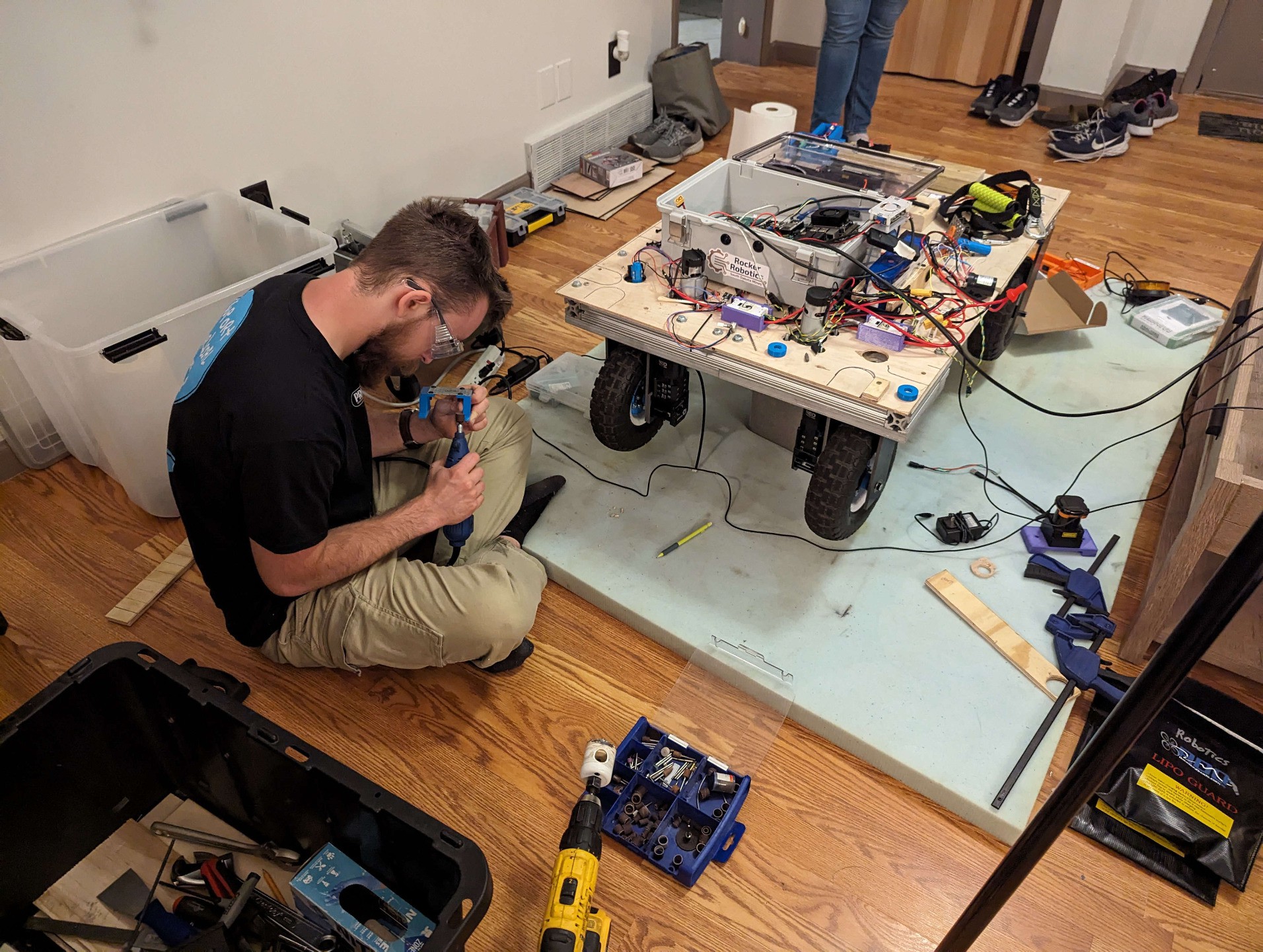
The mechanical sub-team focused on making the robot's frame, chassis, drivetrain, and outer shell. The frame consists of several pieces of 1 ½” T-Slot put together in an “I” shape. This provides much of the support for the drivetrain and electronic components, as well as the payload. Throughout the frame, aluminum brackets and plates are used to help provide support, along with mounting points for other components. The T-Slot also allows the chassis to be modular, allowing elements to be moved and adjusted as needed.
The steering system that was designed is one of the mechanical innovations for this robot. The setup for the steering is similar to a dual-Ackerman system, with the added ability to strafe at a 45-degree angle. Through a set of curved linkages and a rack and pinion system, the turning radius of the robot was decreased to just under 3’. This system also works in tandem with the wheel mounts. Each wheel mount is connected to a linkage by a bolt, which is turned using both the linkages and a set of bearings. While each wheel is driven independently, they are turned simultaneously within pairs.
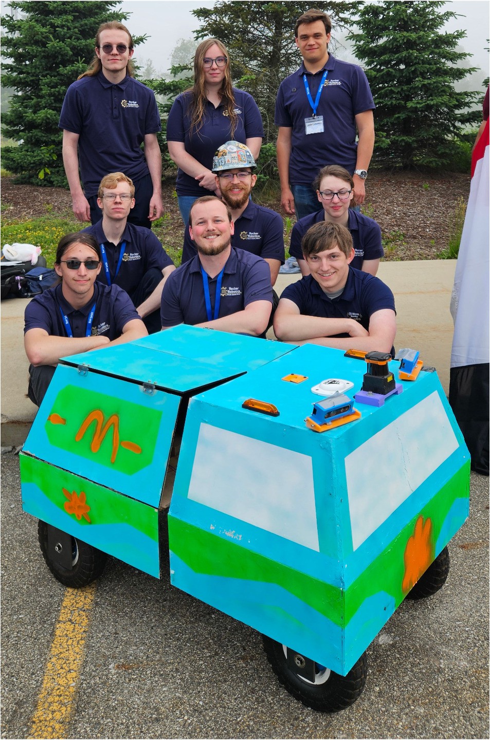
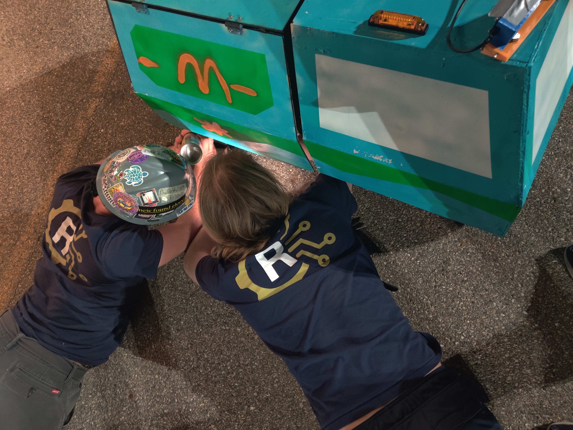
Inspired by Japanese Kei Trucks, the outer shell provides aesthetics, some water resistance, and sensor mounts. The cab was made in several sections, using large-bed 3D printers. Attached to the top is a piece of T-slot that further increases modularity and allows the positions of the sensors to be adjusted as needed. In the bed, there is also a frame to hold the payload, and at the back, a panel for the start and e-stop switches.
Electrical
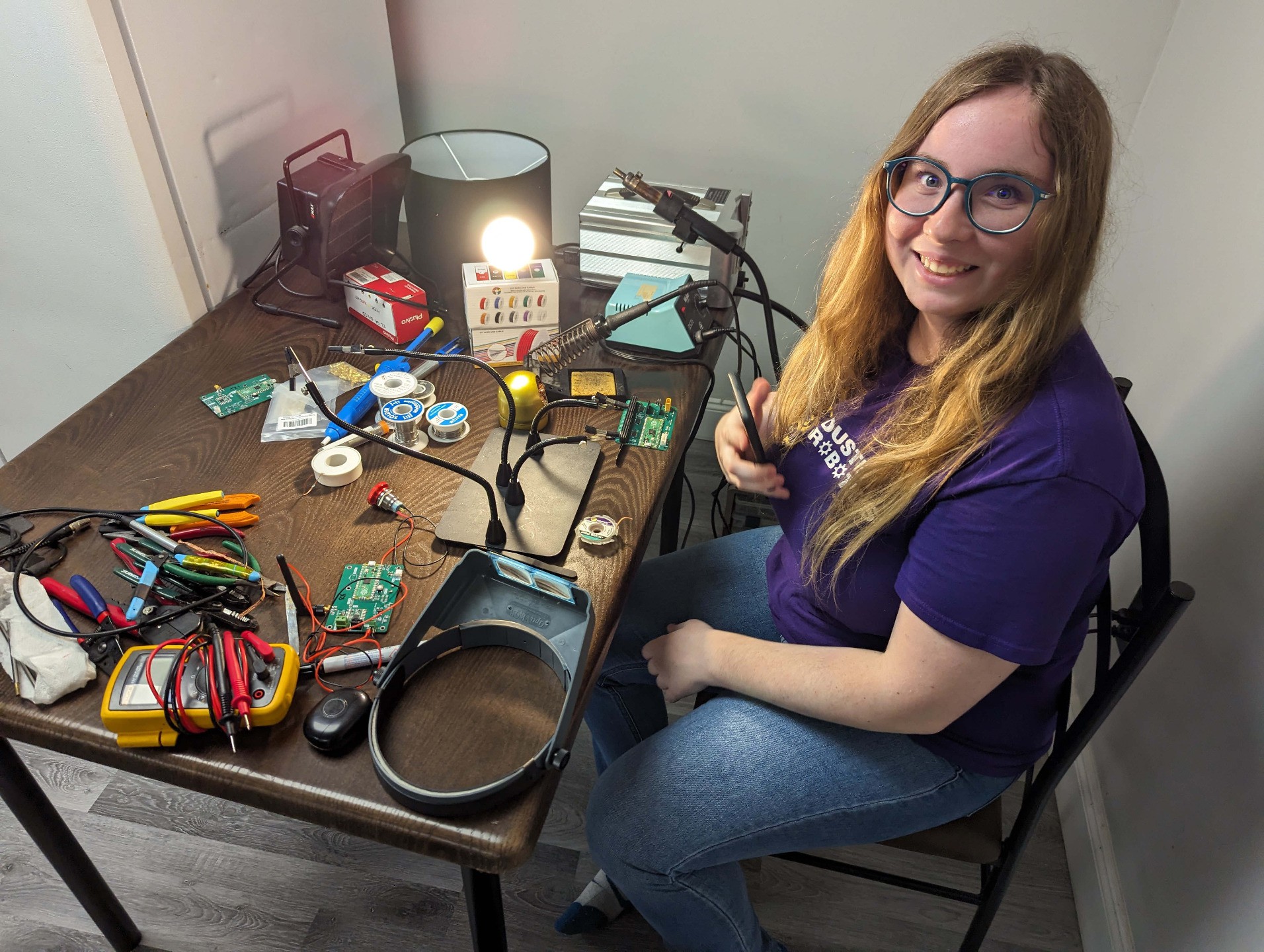
The electrical side of this project mainly dealt with power distribution and establishing the communication system. The robot was powered by a single 4-cell, 20,000 mAh lithium-ion battery. The battery voltage went to the motors directly and was stepped down to 12V and 5V rails for our computers and sensors. The sensor communication and power distribution was done using a custom PCB that held our STM32 microcontroller and connection points for our sensors and controller area network (CAN) bus for controlling our motors. The STM32 was connected over USB to our more powerful Jetson computers. Another custom PCB was designed for our emergency stop system. This one board design could be used as either a remote or receiver. When the emergency stop button was pressed either on the robot or on the wireless remote, the receiver board would open a relay, cutting power to our drive motors and bringing the robot to a stop. The wireless communication between the two e-stop boards was done with Raspberry Pi Picos and 915 MHz radio modules.